 Szarik
Printed & bench-tested
Evidence from real parts.
Actuator and camera work includes physical builds and bench measurements. That evidence applies to the recorded revision and test conditions.
Read the build diary →Build Szarik
A quadruped brings mechanics, electrical systems, electronics and software together. An actuator is a motor and transmission that move a joint. Begin with one actuator, keep a build record, and work through the interfaces one at a time.
Know the starting point
Printed parts, bench experiments and simulation are real. A complete, independently reproducible robot build is still being prepared.
Printed & bench-tested
Actuator and camera work includes physical builds and bench measurements. That evidence applies to the recorded revision and test conditions.
Read the build diary →In simulation
MuJoCo exercises movement and the safety response in a physics model. Whole-robot walking in simulation is separate from a verified physical walking release.
Explore MuJoCo →Still being verified
A complete purchasing list, repeatable motor-construction notes, camera-ribbon compatibility and final speaker mounting still need a coherent builder release.
Ask about your revision →Parts before purchases
A bill of materials, or BOM, is the list of parts and quantities for a build. This overview introduces the major components; use a revision-specific BOM before ordering a full set.
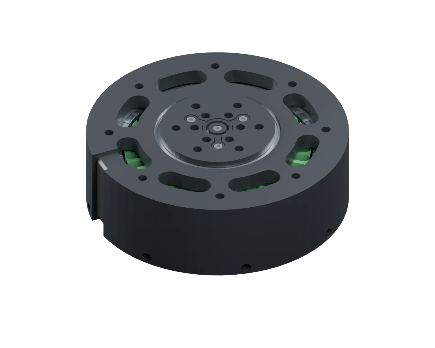
QDD means quasi-direct-drive: a motor with a small gear reduction. Here, six motor turns give one output turn. A driver board controls motor current, and an encoder measures the motor’s angle.
| Component | Quantity | What it does | What to check |
|---|---|---|---|
| Printed QDD actuators | 12 | Joint motors | 6:1 planetary reduction; use a coherent mechanical revision and its motor-construction notes. |
| ERAD 2.1 drivers with AS5048A encoders | 12 | Motor control and rotor sensing | One driver per joint; board revision, wiring and firmware must agree. |
| Raspberry Pi 5 | 1 | Host computer | 64-bit Linux; prepare the host independently of powered joints. |
| ESP32-S3-DevKitC-1-N16R8 | 1 | Spine radio bridge | A motorless controller, distinct from the ERAD driver boards. |
| WitMotion WT9011DCL IMU | 1 | Body orientation sensing | Verify the sensor-axis mapping in the assembled robot. |
| ArduCam B0179 / UC-609 Rev.E cameras | 2 | Stereo vision | The photographed boards have 22 contacts; ribbon pinout and contact orientation still need revision-specific verification. |
| ReSpeaker XVF3800 with XIAO ESP32S3 | 1 | Head microphone array | Preserve the printed camera carrier and the selected head interfaces. |
| Seeed 114993346 speaker | 1 | Head audio output | Selected speaker; connector mating and full mounting fit remain unverified. |
| Bosch ProCORE18V battery system | 1 | Motor power source | Protection, e-stop, battery interface and supply wiring belong to the electrical build. |
| Bearings, belts, fasteners and heat-set inserts | Per revision BOM | Mechanical hardware | Use the revision-specific bill of materials; this overview is not a complete purchasing list. |
The camera boards photographed for this project are UC-609 Rev.E with 22 contacts. Connector width alone does not prove ribbon pinout or contact orientation.
Prepare the workbench
Saved project estimates use H2S 0.4 mm profiles. Re-slice for your own machine; print time and fit depend on the settings.
Meet the design tools →Work in small milestones
Keep the mechanical, electronics and firmware revisions together. A new drawing or test result can change the next step.
Identify the printed housing and gears, bearings, magnets, inserts and driver board. Learn what the 6:1 reduction does before repeating it twelve times.
Explore the actuator →With motor power disconnected, check the chosen parts and purchased hardware against the same revision. Record interference, inaccessible screws and unverified fits before printing a full set.
Check the belt path, tensioning, covers and clearances with power disconnected. A leg combines three actuators; the belt transmission is another interface to verify.
Look inside the leg →Review battery retention, protected power distribution, electronics access and cable routes. Preserve the tested camera carrier; verify camera ribbons and the speaker interface before treating them as interchangeable parts.
Explore the head →The host is a Raspberry Pi 5 with 64-bit Linux. Raspberry Pi OS Lite is the preferred starting point; an existing working Ubuntu LTS installation can also be used. Host tools use Rust and Python; board firmware uses Arduino C++.
Raspberry Pi setup guide →Powered tests require a tested hardware motor-power stop, configured limits, a supported mechanism and a clear workspace. Progress from one joint to one leg before attempting a complete robot.
Read the open safety item →Useful files, available now
Download the major-parts overview and a planning checklist. Both label unresolved interfaces and the boundary between preparation and powered testing.
CSV · spreadsheet-friendly
Major components, quantities, roles and revision checks.
Download parts overviewMarkdown · editable text
Workshop preparation, subsystem milestones and open safety work.
Download checklistA complete public build bundle is still in preparation. The source repository is private. These planning files are available today; a complete print-ready package will need a matching BOM, assembly instructions, firmware and fit verification.
The actuator is based on an external 3D-printed QDD actuator project. Its files describe that upstream project rather than a verified Szarik release.
Build in the open
Include the subsystem and revision, what you expected, what you observed, and relevant photos or logs. Remove credentials and personal details before sharing.